by Ward R. Malisch, PhD, PE, and Bruce A. Suprenant, PhD, PE
Division 03 specifies concrete floor surface flatness requirements to be installed by the concrete contractor. Division 09 specifies the concrete floor surface flatness for the flooring installer that must be met before installing the floorcovering. What does it mean when these requirements are incompatible?
One of the inconsistencies is Division 03 requires the floor flatness to be measured within 72 hours after concrete placement, whereas Division 09 requires the floor flatness to be measured before the floorcovering installation, which may be six to 12 months after the concrete placement. Additionally, Division 03 requires floor flatness to be measured using F-numbers, while Division 09 usually requires floor flatness to be measured as an allowable gap under a 3.1-m (10-ft) straightedge.
Further, Division 03 requires floor flatness not be measured across a construction joint or within 0.6 m (2 ft) of any slab edge, column blockout, or slab penetration. However, Division 09 requires floor flatness to be measured at all these locations. At the same time, Division 09 includes multiple but different floor flatness requirements for carpeting, vinyl, wood, and ceramic tile.
The owner does not want a specification battle; he or she just needs a concrete slab that allows the floorcovering to be installed to achieve a good appearance and obtain the manufacturer’s warranty. Clearly, there must be a cost-effective and efficient solution. Cooperation between the American Society of Concrete Contractors (ASCC) and six associations has led to a solution for bridging the specification gap between Divisions 03 and 09.
Floor flatness is initially measured within 72 hours after concrete placement using F-numbers to determine contractor’s compliance with Division 03 specifications.Flooring installers need a floor flatness metric when they arrive onsite to install flooring in compliance with Division 09specifications. However, because concrete floor flatness decreases with time due to curling or deflection, the initially fl at floor placed by the concrete contractor is unlikely to meet the floor covering specification requirements.
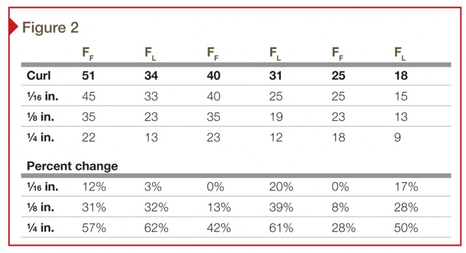 The effect of the amount of curling on floor flatness and levelness for a concrete slab with a 4.6-m (15-ft) joint spacing and initially finished to a moderately fl at (FF 25), fl at (FF 40), and a very fl at (FF 51) floor.
Defining the gap
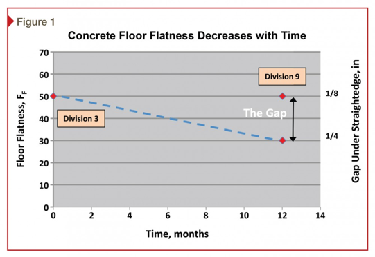
The gap between floor flatness requirements is illustrated in Figure 1. The concrete contractor produces a floor that meets F-number flatness requirements included in Division 03 and measured shortly after concrete placement. The floorcovering installer arrives onsite far later to start preparation for floor installation. The floor flatness for a concrete slab-on-ground decreases with time due to curling caused by non-uniform concrete drying shrinkage. The floor flatness for an elevated concrete slab decreases with time due to initial deflection caused by the slab’s dead weight and long-term deflection due to creep and shrinkage of the concrete.
The time between the concrete contractor’s work and the flooring installer’s preparation results in a surface change that is the most significant factor in creating the ‘gap.’ Thus, while the specifications may require a suitable concrete surface as placed and finished by the concrete contractor, the resulting changes in surface shape make it unsuitable when the flooring installer arrives onsite. This decrease in flatness often requires flooring installers to do more surface preparation than they originally planned.
It is often impossible to estimate the degree to which floor flatness changes with time, and to determine when the flooring installation might proceed after concrete placement. As will be shown, the gap might be small (e.g. a slight reduction in floor flatness) or significant (e.g. more than a 50 percent reduction in floor flatness based on F-numbers). Thus, it is difficult for flooring installers to decide how much money to put in their bid for surface preparation. It is also difficult for owners to determine how much they need to pay to receive a high-quality final floor finish.
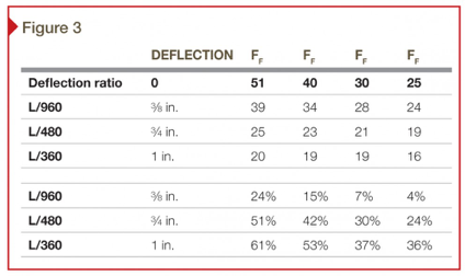
Modeling the effect on floor flatness and levelness of elevated slab deflection.
Why the gap exists
Four factors contribute to the gap between the concrete contractor’s finished floor and the flooring installer’s requirements:
- changes in floor flatness due to curling and deflection;
- differences in floor flatness measurement methods;
- differences in floor flatness measurement locations; and
- dealing with multiple floorcovering requirements.
Changes in floor flatness due to curling
Concrete slabs built flat do not stay flat. The foreword of American Concrete Institute (ACI) 302.1R-04, Guide for Concrete Floor and Slab Construction, states it is completely normal to expect some amount of curling on every project.
Slab curling is caused primarily by differences in moisture content or temperature between the top and bottom of the slab. The slab edges curl upward when the surface is drier and shrinks more, or is cooler and contracts more than the bottom. Curling is most noticeable at construction joints, but it can also occur at saw-cut joints or random cracks. Curling usually results in part of the slab edges and corners losing contact with the underlying base.
There are many factors that influence the amount of curling for a concrete slab-on-ground.1[6] One of the most important factors is the relative humidity (RH) of the drying environment for the concrete slab. For instance, a concrete slab-on-ground in New Orleans, Louisiana, at 90 percent RH might undergo differential drying shrinkage gradient from the top to bottom surface of as little as 60 x 10-6 in./in. (or mm/mm). While the same concrete slab in Denver, Colorado, exposed to 30 percent RH would undergo a differential shrinkage gradient from the top to the bottom surface as much as 200 x 10-6 in./in.
The magnitude of the shrinkage gradient is three times larger for the slab in Denver versus New Orleans; thus, we would expect a slab to curl more in the former than the latter. Other factors that influence the amount of curling include:
- potential drying shrinkage magnitude of the concrete mixture;
- modulus of subgrade reaction;
- concrete compressive strength and modulus of elasticity;
- reinforcement ratio;
- slab thickness; and
- joint spacing.
Poor curing is often cited as the culprit when a slab curls. ACI 360R-10, Guide to Design of Slabs-on-Ground, states:
Extended curing only delays curling, it does not reduce curling.
In 2003, one of this article’s co-authors reported on F-number floor surface measurements taken at the same location lines at different times on two projects:2[7]
- a 150-mm (6-in.) thick, 28-MPa (4000-psi) concrete slab containing 19-mm (¾ in.) maximum aggregate size placed directly over a vapor retarder for a gym floor at the University of Maryland; and
- a 150-mm (6-in.) thick slab with 28-MPa concrete placed on a compactible granular base with saw-cut joints every 4.6 m (15 ft) for an industrial warehouse in Pennsylvania.
Measurements for the gym floor were made 72 hours after concrete placement, and then again seven months later when the flooring installer arrived onsite. The measurements indicated the floor flatness had decreased by 20 percent during the seven months. Similarly, measurements for the industrial slab were taken with 72 hours after concrete placement and then again 12 months later. The measurements indicated floor flatness decreased by 40 percent during that year—this shows the magnitude of floor flatness changes that must be accounted for in bridging the specification gap between Divisions 03 and 09.
The length of lost contact area as a result of curling is about 20 percent of the joint spacing at each end of the slab. For a 4.6-m (15-ft) joint spacing, the slab curl would be expected to change the profile for about 1 m (3 ft) from each end. It is possible to take F-number readings from floors with differing profiles, download those values into a spreadsheet, then add a known amount of curl, and calculate new F-numbers. This allows a comparison of F-numbers before and after the curl.3[8] Good agreement with this approach was found when compared to the actual F-number measurements for the gym floor and industrial slab.
Figure 2 gives the analytical results showing the effect of the amount of curling on floor flatness and levelness for a concrete slab with a 4.6-m (15-ft) joint spacing and initially finished to a moderately flat (FF 25), flat (FF 40), and a very flat (FF 51) floor as defined by ACI 117-10, Specification for Tolerances for Concrete Construction and Materials.
The amounts of curling considered were 1.6, 3.2, and 6.4 mm (1/16, 1/8 and ¼ in.). A 1/8-in. curl will decrease the floor flatness from an FF 51 to an FF 35, while that same amount of curl will only decrease the floor flatness with an initial FF of 25 to a final FF of 23. As the table shows, the effect of curling is more pronounced on floors with higher initial floor flatness and levelness values. Thus, specifying and paying for higher floor flatness and levelness values in Division 03 may not prove to be a cost-effective solution.
Changes in floor flatness due to deflection
Division 03 requirements state the floor flatness and levelness of elevated slabs must be measured within 72 hours after concrete placement and while the concrete is still supported by the formwork and shoring. However, as soon as the formwork and shoring is removed, the slab deflects downward due to its dead weight. The deflected slab shape changes the floor flatness and levelness, just as curling does.
The concrete industry treats deflection as two parts:
- initial deflection due to dead weight of the structural members; and
- long-term deflection due to concrete creep and shrinkage.
ACI 318-11, Building Code Requirements for Structural Concrete, can be used to estimate the additional long-term deflection at 12 months as about 1.4 times the initial deflection. For example, a concrete flexural member spanning 9.1 m (30 ft) was designed for an initial deflection limit of L/360, where L is the span length in inches. Thus the initial deflection would be 30 x 12/360 = 1 in. (about 25 mm). The additional long-term deflection as estimated in accordance with ACI 318 would be 1.4 x 1 = 1.4 in. (about 36 mm) of additional deflection. If the flooring installer arrives one year after the concrete has been placed, he or she could thus expect to see a slab that has deflected about 2.4 in. (about 60 mm).
The effect on floor flatness and levelness of elevated slab deflection can be modeled in the same fashion as the curling effect was for concrete slabs-on-ground. First, initial F-number profiles were simulated, representing varying floor quality, and then superimposed structural deflection values on the profiles. The deflection was assumed to vary with position along the beam as a sine wave, with the initial deflection equal to L/360, L/480 and L/960–deflection values typically used in building code requirements, where L is the length of the span. The deflections were calculated at (1-ft) increments along the beam and added to the simulated F-number readings at the same increment. A 9.1-m (30-ft) span was assumed and the analytical results of this approach are shown in Figure 3.
The analysis shows that for a stiff structure with an FF 25 value, a deflection of L/960 (3/8 in. for a 30-ft span [about 9.5 mm for 9.1 m]), FF decreases by only four percent. Even for an initial profile representing an FF 30 floor, a deflection of L/960 affects the FF value by only about seven percent. However, for an initial FF value of 50, the L/960 deflection causes about a 24 percent decrease in flatness. As is the case with curling deflection—the higher the initial FF value, the greater the effect of dead-load deflection.
A composite overall flatness of FF 35 is the maximum specified value typically used for elevated slabs (ACI 302.1R-04). Based on the analysis, and at this specified value, a deflection of L/960—which indicates a stiff building—will probably result in an FF reduction no greater than about 10 percent. Unfortunately, the same cannot be said for deflection values of L/480 and L/360, which are common for structural steel framing systems supporting concrete slabs placed on metal decking. Since these slabs deflect much more than slabs in reinforced concrete frame buildings, the effect of deflection on FF can also be expected to be greater.
Differences in floor flatness measurement methods
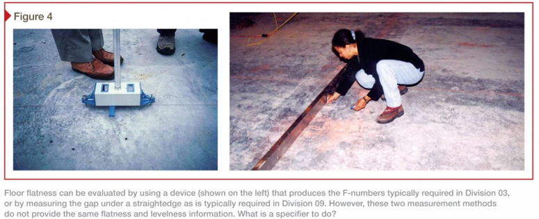
Division 03 floor flatness and levelness requirements are usually specified with the F-number system and thus are measured in accordance with ASTM E1155, Standard Test Method for Determining FF Floor Flatness and FL Floor Levelness Numbers. Division 09 floor flatness is usually specified as a maximum allowable gap measured under a 3.1-m (10-ft) straightedge that rests on two high spots on the concrete surface. It is important to note the straightedge method measures only floor flatness and not levelness. Figure 4 illustrates the two different measurement methods.
If correlations between F-numbers and straightedge gaps are used, it is important to understand the F-number for a given straightedge gap can vary widely. The table in Section 4.5.6 of ACI 117-90 indicates a 3.2-mm (1/8 in.) gap under a 3.1-m (10-ft) unleveled straightedge is roughly equal to an FF 50. However, the standard’s Commentary states:
there is no direct equivalent between F-numbers and straightedge tolerances; the following table does give a rough correlation between the two systems.
Although there is a caution in the ACI 117-90 Commentary, most people use the table because it provides a simple method for comparing the two measurement methods.
The Commentary in ACI 117-10 contains further information on the correlation between the two measurement methods by stating a specified maximum gap of 3.2 mm (1/8 in.) under a 3.1-m (10-ft) straightedge could be equivalent to FF numbers ranging from 38 to 110. The F-numbers are sensitive to the number of 3.2-mm (1/8-in.) gaps, or waves, in the floor. As the number of waves in a 3.1-m (10-ft) length increases, the FF number decreases. This feature of the F-number measuring system enables specifiers to differentiate among floors with the same measured gap but with different numbers of waves.
The two different methods measure significantly different surface properties. Thus, even if concrete contractors satisfy Division 03 F-number requirements, and the floor does not change with time, flooring installers are unlikely to find their gap under the 3.1-m (10-ft) straightedge satisfies the Division 09 requirements. Additionally, there are still specifications with major floor flatness discrepancies—for example, specifying an FF of 20 in Division 03, but then specifying a Division 09 requirement of a 3.2-mm (1/8-in.) maximum gap under a 3.1-m (10-ft) straightedge.
Differences in floor flatness measurement locations
Although the concrete industry lauds F-numbers as a more precise approach to specifying floor flatness, the F-number measuring method does not meet the floorcovering industry’s needs. For instance, according to ASTM E1155 and ACI 117 the measurement should not be taken:
- across construction joints;
- within 0.6 m (2 ft) of a penetration; and
- after 72 hours.
However, to provide the owner with a satisfactory floor finish, the floorcovering must be placed over construction joints and near penetrations on a floor that is certainly older than three days. Figure 5 shows a straightedge being used to measure the flatness directly across a construction joint and at the intersection of a column blockout and the floor slab. F-number measurements do not reflect the flatness variations indicated by the straightedge at these locations.
Although ASTM E1155 includes a procedure for measuring across construction joints, it is rarely used. If the floorcovering industry were to adopt F-numbers, the measuring method and acceptance criteria would have to change so measurements could be made at any location on the floor.
Dealing with multiple floorcovering flatness requirements
Owners and architects often specify multiple floorcovering products for use in facilities such as retail stores. The floor flatness requirement for each of these products can differ greatly. For instance, the Carpet & Rug Institute’s (CRI’s) 2011 Carpet Installation Standard does not have a floor flatness requirement. In contrast, the American National Standards Institute/Tile Council of North America (ANSI/TCNA) A108-2013, Specifications for the Installation of Ceramic Tile, states:
Tiles with all edges shorter than [380 mm] 15 in., shall have a maximum permissible variation of [6.4 mm in 3.1 m] ¼ in. in 10 ft from the required plane, and no more than [1.6 mm] 1/16 in. variation in [300 mm] 12 in. when measured from high points in the surface. For tiles with at least one edge 15 in. or longer, the substrate shall have a maximum permissible variation of [3.2 mm] 1/8 in. in 10 ft from the required plane, and no more than 1/16 in. variation in [610 mm] 24 in. when measured from the high points in the surface.
Floor flatness requirements for the Division 09 finishes vary for each specific floorcovering. Thus, it is possible to be comparing a Division 03 floor flatness specification with multiple Division 09 floor flatness specifications. To get the best price for owners, and meet their schedule, the concrete contractor must place 1400 to 3700 m2 (15,000 to 40,000 sf) of concrete daily. It is not feasible to have the concrete contractor meet separate floor tolerances and finish requirements for every area where a different floorcovering product will be used. Often, the owner has not even made the flooring product choices for different locations before the concrete slab is placed. Thus, Division 09 is unavailable.
Engineers often choose the floor flatness specification in Division 03 with or without input from the architect. The architect needs to give input to balance the needs of the floor flatness requirements for the specified floorcoverings. It might not be economical to just choose the highest floor flatness requirement for Division 09 and put that in Division 03 because, as previously shown, floor flatness decreases with time. Thus, the extra cost passed from the concrete contractor to the owner for achieving a flatter floor may not be of benefit to the flooring installer 12 months later. It may also not be economical to specify the lowest concrete floor flatness needed because that may increase the cost of grinding and patching later.
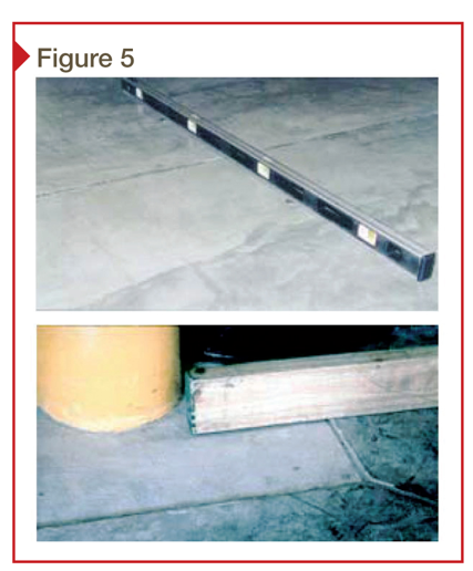
Flooring installers need to measure flatness with a straight edge that crosses construction joints, column blockouts, and near penetrations. F-numbers measured in accordance with ASTM E1155 will not yield this information. The top photo shows a carpenter’s level placed across a construction joint and the bottom photo shows a straightedge being used to check flatness at a column blockout.
The engineer selects a design methodology to keep the floor flat with time. Possible design options include use of post-tensioning, shrinkage-compensating concrete, increased non-prestressed reinforcement (about 0.5 to 0.6 percent instead of the typical 0.1 percent), macrofibers in the dosage range of 3 to 4 kg/m3 (5 to 7 lb/cy), concrete drying shrinkage limits, and shrinkage-reducing admixtures (SRAs)—or a combination of these alternatives.
Options for closing the gap
There are numerous options for closing the gap between Divisions 03 and 09 floor flatness specifications, but this article focuses on three:
- design a long-term flat floor;
- specify higher initial floor flatness; and
- grind and patch as needed.
The goal is to balance the owner’s cost for producing the desired floorcovering quality by choosing one option or a combination of options.
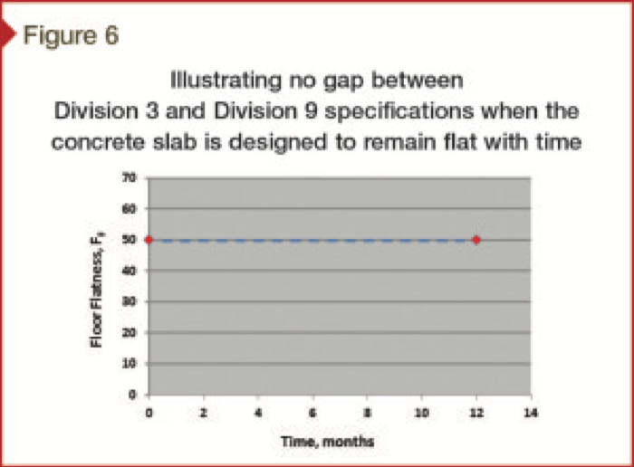
Design a long-term flat floor
As shown in Figure 6, the goal is to design the floor to stay flat over time. ASCC Position Statement 30, Responsibility for Controlling Slab Curling, indicates both ACI and the Canadian Standards Association (CSA) recognize curling control is the designer’s responsibility. In 2003, when ASCC Position Statement 6, Division 3 versus Division 9 Floor Flatness Tolerances, was first published, there was not enough technical information or design experience for most engineers to design a floor to remain flat until the flooring installer arrived on site.
In 2014, however, some engineers are designing floors that remain flat by using one or more of the following options:
- limit concrete drying shrinkage;
- use shrinkage reducing admixtures;
- lower concrete compressive strength;
- use more non-prestressed reinforcement (from 0.5 to one percent);
- use 3 to 4-kg/m3 (5 to 7-lb/cy) macrofibers in the concrete;
- use shrinkage-compensating concrete; and
- use post-tensioning.
All these options could be used for concrete slabs-on-ground to control curling, but some will be of limited value when controlling deflection for elevated slabs. Many engineers are not yet comfortable with the risk of designing a flat floor that stays flat, and will avoid this option.
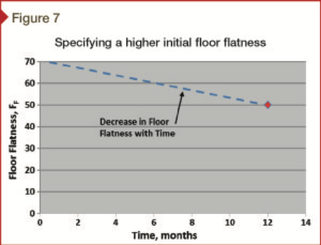
Specify higher initial floor flatness
As shown in Figure 7, the specifier could ask the concrete contractor to produce a higher initial floor flatness with the intent that when the flatness decreases with time, it will still be usable without further remediation for the flooring installer. Most design teams are reluctant to employ this option as they are unsure of how much the floor flatness will decrease with time and when the flooring installer might arrive onsite.
When this strategy is pursued, there is a cost increase to the concrete contractor to provide the higher floor flatness. However, there remains a risk the floor flatness will decrease more than estimated, which means some grind and patch might still be necessary.
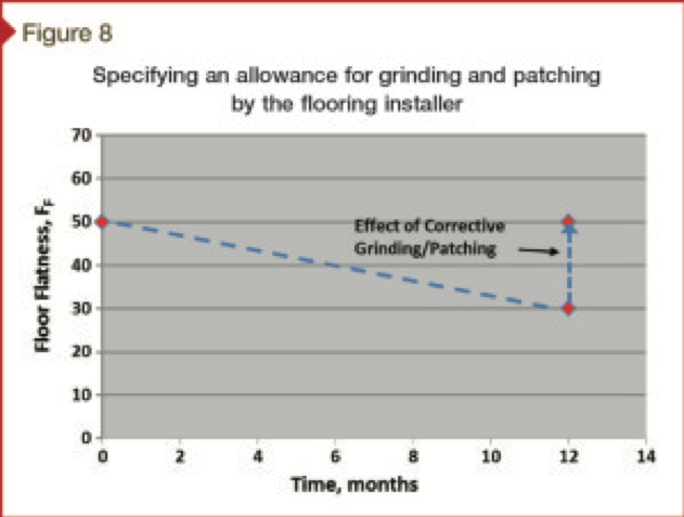
Grind and patch as needed
As shown in Figure 8, the concrete floor is designed as economically as possible (while balancing other design and owner concerns), before grinding and patching as needed to achieve the necessary flatness when the flooring installer arrives.
The cost of grinding and patching can add up to more than $100,000 on multi-story buildings. Some owners believe this is an unnecessary expense, but there are options for cost allocation. In other words, some design teams prefer to use an allowance the owner budgets at the start of the project. If the allowance is not needed, the owner keeps the money.
The money could also be spent in designing and constructing to keep the floor flat with time. However, this is a risk when the money is used in designing and building a flat floor that does not stay flat. In that case, the owner will be spending money twice—once for the flat floor option and then more for grind and patch as necessary to achieve a flat floor before floorcovering installation.
The engineer estimates the decrease in floor flatness with time, then specifies an initial FF that later drops to the value needed by the floorcovering installer. Making the estimate is not easy because the amount of curling varies with the concrete properties and service environment. Also, the higher the initial specified FF, the greater the percentage loss in floor flatness for a given amount of curling. Thus, the concrete contractor might be paid more to produce an initially flatter floor that does not benefit the floorcovering installer because the amount of curling exceeds that anticipated by the engineer.
Engineers design the floor knowing flatness will change with time, but also specify grinding and patching to bring the floor flatness back to the desired level. To obtain competitive and comparable bids, they include an allowance in the contract for the cost of grinding and patching. The owner controls the allowance and thus benefits when little or no grinding or patching is required.
Specifying an allowance to bridge the gap
Since 2003, when ASCC Position Statement 6 was published, the ‘grind-and-patch-as-needed’ option has been used most often. The design team budgets it as an allowance so the owner need not spend the money if the concrete slab-on-ground or the elevated concrete slabs remains as flat as required by the flooring installer. The owner can then decide before flooring installation whether to use the allowance to ensure the desired quality of finished flooring.
The other benefit of this option is its adaptability to the requirements for different floorcoverings. For a concrete slab to receive carpeting, perhaps no preparation would be needed. However, for a concrete slab to receive 460 mm (18-in.) square ceramic thin-set tile, money used for prep work may be well spent.
Notes
1 One of this article’s co-authors—Bruce Suprenant—wrote a two-part article for ACI’s Concrete International in the spring of 2002. See “Why Slabs Curl?Part I: A Look at the Curling Mechanism and the Effect of Moisture and Shrinkage Gradients on the Amount of Curling” and “Why Slabs Curl?Part II: Factors Affecting the Amount of Curling.” (back to top[13])
2 See Suprenant’s July 2003 Concrete International article, “The Floor Tolerance/Floorcovering Conundrum.” (back to top[14])
3 See the authors’ Tolerances for Cast-in-Place Concrete Buildings (American Society of Concrete Contractors, 2009). (back to top[15])
Ward R. Malisch, PhD, PE, is concrete construction specialist for the American Society of Concrete Contractors (ASCC), an Honorary Member of the American Concrete Institute (ACI), and a member of ASTM International. He has been active in the concrete construction industry for more than 50 years, and has received the ASCC Lifetime Achievement Award, the National Ready Mixed Concrete Association’s (NRMCA’s) Richard D. Gaynor Award, and the Silver Hard Hat Award from the Construction Writers Association. Malisch can be reached at wmalisch@ascconline.org[16].
Bruce A. Suprenant, PhD, PE, is the technical director for the American Society of Concrete Contractors (ASCC) and a Fellow of the American Concrete Institute (ACI). He has taught concrete materials, construction, and structures for 15 years in universities and has been a consultant in that field for 20 years. Suprenant received ACI’s Roger Corbetta Construction Award and has authored or coauthored more than 100 articles and papers, including one that received ACI’s Construction Award in 2011. He can be reached at bsuprenant@ascconline.org[17].
Endnotes:
- [Image]: http://www.constructionspecifier.com/wp-content/uploads/2014/10/Casino-15.jpg
- [Image]: http://www.constructionspecifier.com/wp-content/uploads/2014/10/CS_October_2014_HR-11.jpg
- [Image]: http://www.constructionspecifier.com/wp-content/uploads/2014/10/CS_October_2014_HR-12.jpg
- [Image]: http://www.constructionspecifier.com/wp-content/uploads/2014/10/CS_October_2014_HR-14.jpg
- [Image]: http://www.constructionspecifier.com/wp-content/uploads/2014/10/CS_October_2014_HR-16.jpg
- 1: #note1
- 2: #note2
- 3: #note3
- [Image]: http://www.constructionspecifier.com/wp-content/uploads/2014/10/CS_October_2014_HR-18.jpg
- [Image]: http://www.constructionspecifier.com/wp-content/uploads/2014/10/Figure6.jpg
- [Image]: http://www.constructionspecifier.com/wp-content/uploads/2014/10/Figure7.jpg
- [Image]: http://www.constructionspecifier.com/wp-content/uploads/2014/10/Figure8.jpg
- top: #note4
- top: #note5
- top: #note6
- wmalisch@ascconline.org: mailto:%20wmalisch@ascconline.org
- bsuprenant@ascconline.org: mailto:%20bsuprenant@ascconline.org
Source URL: https://www.constructionspecifier.com/bridging-the-specification-gap-between-divisions-03-and-09-concrete-and-floorcovering-associations-unite/
Copyright ©2018 Construction Specifier unless otherwise noted.